
As everybody knows, console cables and their corresponding interfaces are a scourge on a network administrators existence. They are always too short, COM-ports get renumbered, Baud-rates are unknown, etc. By their very nature, you also have to be physically present in the vicinity of the box you’re trying to configure. Today we’re going to change all that, by constructing a wireless console cable adaptor with almost infinite range.
I can almost here people shouting something about SSH and Telnet to their screens, as well as something about the Airconsole. First and foremost, telnet and SSH are both wonderful, after you’ve configured the device, but for initial setup, they sadly can’t be used. Airconsole is quite nice, and I use it almost daily, but it’s useful when you want to sit somewhere comfortable when configuring a device in the same room as you, not so much when you want to be comfortable on a beach half a world away from the offending device.
This we’re going to change today, with one device, the B+B SmartFlex router.
First a quick word about the SmartFlex routers. They are these small IoT routers that can be had in a multitude of configurations, for example with 3G/4G WAN interfaces, RS232 ports, PoE enabled Ethernet ports, binary I/O and so on. Today we’ll be using one that has a LTE WAN interface and a RS232 port.
The idea here is to use the router as a console adaptor, that we can then remotely access from anywhere we like (preferably warm and comfy)! This guide won’t cover how to access the router, you have multiple options there (an APN from your mobile operator, OpenVPN tunnel back to your main firewall etc.) and they are quite specific to how your network has been set up. But we’ll cover how to get the remote console over the serial port working!
Making the Cable
To start of with, we’ll need a console cable. Most gear these days use what I like to call “the blue Cisco cable”. This is a DB9 to RJ45 cable that’s used to access the console on almost all network gear with a RJ45 console port. The slight issue is that the SmartFlex routers doesn’t come with a DB9 port, it would take up too much valuable space, so depending on which version you order, you can either get a RJ45 port or terminal block connectors. I’ll be using a screw connector version in this guide, because it’s easier to make a cable for it, but if you want a nice and tidy package I’d say go with the RJ45 version.
This means we will have to make a cable for this router, and for that we need to know the pinouts of the two ports at both ends of the connection. The device side we can get sorted by copying the “blue Cisco” cable’s RJ45 end, and the other pinout we’ll get from the SmartFlex manual.
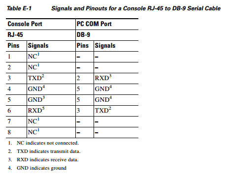
As you can see, even though the cable has 8 pins, we’re actually using 4 of them, and they only carry 2 signals, TX and RX.
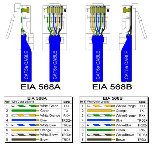
As one end is supposed to be a RJ45, we can use an ordinary network cable to speed up our cable making process. Cut of one end, and peel back the outer jacket to reveal the individual wires. We can then use the pinout for a network cable to identify which wires carry our signal. First you need to figure out if the cable is wired according to the A or B standard. Then the wires are quite easy to figure out; the both blue wires are GND (ground), the white orange or white green are TX and orange or green is RX.
We then need to match up the TX and RX wires with their corresponding pair on the SmartFlex router. RS232 in it’s simplest 3-wire configuration, which we’re using here, relies on two wires to carry signals and a common ground wire. One device sends data on it’s TX line to the other device, which receives the data on it’s RX line, and vice versa. We therefore need to match the devices TX line with the routers RX line and again vice versa.
The next step depends on which SmartFlex version you have. We’ll start with the one I’ve got, the terminal block version:

As you can see, we need to connect terminal 3 to the two blue wires, terminal 4 to the white orange or white green wire, and finally the orange or green wire to terminal 5. You can see that the SmartFlex also has CTS and RTS terminals. These are used by more sophisticated devices to signal to each other when the other side can send or receive data. If your devices has them, you would connect them crossed just the same way as the RX and TX wires. Console cables normal doesn’t bother with them, so we won’t bother with them.
If you happen to have the RJ45 version of the SmartFlex router, then making the cable will be a bit more complicated, as you either need to crimp on a new connector to one end of the network cable, or cut the cable in the middle and cross the wires correctly there. I won’t explain which wire needs to connect to which, but below is a pinout of the RJ45 RS232 port on the SmartFlex from which it shouldn’t be to hard to work out how to construct the cable.

Here you can see that the SmartFlex makes full use of the 8 pins in the RJ45 connector with even more signals. I won’t go into detail what all of these do, but it’s basically even more signalling pairs for data flow control.
Configuring the Router
The next step is to configure the SmartFlex router so that it’ll forward TCP data out on the RS232 interface.
First, log into the management interface of the router (default configuration is 192.168.1.1 and credentials root/root).
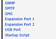
Here you’ll select “Expansion Port 1” in the menu to the left
This will open up the page where you can configure the settings you want

As you can see, you can choose the parameters of the serial connection. The ones listed here are the typical ones you would use for almost every network device, be it a Cisco switch or a HP router.
Next is the Split Timeout which is how long the router will wait for you to stop sending data on the TCP port before it empties it’s buffer out on the serial interface. For our console purposes this doesn’t really matter, so leave it at the default 20.
Protocol lets you choose between TCP or UDP, for our purposes TCP will be fine.
Mode sets if the router should listen on incoming connections or establish a connection to another server or device. The whole purpose of this guide is to connect to the router from our beach chair in Aruba, so we will select server
TCP Port sets the port the router will listen to incoming connections on. In my case I’ve set it to 12345 but you can set it to whatever you like as long as it’s not a port in use by some other function on the router or something behind it’s NAT and firewall. Remember to open up the port in the firewall if you want to access it from the WAN.
The rest of the settings doesn’t really matter for our intents and purposes, so we’ll leave them at the defaults.
Connecting to the Limitless Console Cable
So, we now have our wireless, 4G enabled console cable, but how do we connect to it? Easy, just open a TCP session to the router on the port we prepared earlier!
I can, again, hear the audience go; “Well, how do I go about doing that then?”.
It’s equally easy, opening a TCP session on a port of a remote host actually means; just Telnet to the port. (Pro tip; wanna know if a port is open? Just telnet to it!)
Fire up Putty, and select telnet and the port you configured (12345 in my case)

And if everything went as it should you should now be presented with the console of whatever device you connected the console cable to!

In my case, a rather crummy HP 2510G-24 with equally crusty firmware in it.
A couple of caveats;
This session behaves a bit funnily when it comes to every character on you keyboard other than letters, number and Enter. Tab and Space for example needs you to hit Enter after you type it before it’s sent out the serial interface, making Tab complete a bit of a nightmare on HP devices for example. I’m fairly certain this has something to do with how the router takes TCP input (aka. Telnet) and translates that into data sent out on the serial line. I’m trying my best to find a solution to the problem, and I’ll update the guide accordingly if I ever find out how to fix it. That being said, this isn’t such a problem as one might imagine. The idea isn’t to completely configure the device over this “extended” console session, but to get enough configuration into the device so that it can communicate with the network, and thus be reachable by more conventional means such as telnet or SSH. And for this purpose, I think it works splendidly!

Leave a comment