As most of my European readers are keenly aware, the current energy situation in Europe is rather precarious. Rolling blackouts are something that might need to be implemented to keep the grid operational during the coming winter months. While this in itself isn’t such a big deal, being without power for 1 hour at a time isn’t the end of the world. However, I would rather not burn up my electronics from the spikes generated by the switching events in substations, and the hour-long blackouts are infinitely more bearable if my WiFi stays up. So, I’ve procured an UPS (Uninterruptible Power Supply) for my network equipment.
However, the fans in it are simply unbearable monsters that spin at 4500 rpm while producing around 60 dB of noise. These fans, made by Sanyo Denki, are from a reliability point of view simply amazing, I’ve seen them run for decades without missing a beat. However, they are not designed for a home environment, and the sound levels are unacceptable. So the fans had to go.
I replaced them with Noctua’s Redux 80mm 1800 rpm fans. They are comparatively silent, and move around 60% of the air moved by the Sanyo Denkis (53 m3/h vs 90 m3/h). I however will run the UPS at around 10% of its rated power, and it’ll be in a nice 23 ℃ home environment, not a 45 ℃ network cabinet, so I think it’ll be alright.
The original fans use a different connector, so I just snipped the connectors off of the old fans and soldered the three wires together. One issue crept up however, after replacing them the UPS complained about a fan fault.
After som research, I found out that the Sanyo Denki fans aren’t your normal type of computer fan. A normal PC fan sends out a PWM signal on the yellow wire, telling the computer what the rotational frequency of the fan is. The Sanyo Denkis however, implement something called a “locked rotor sensor” on the same third yellow wire. This feature is implemented a bit backwards, where the UPS outputs a voltage (less than 27.6VDC according to Sanyo Denki’s documentation) through a current limiting pull-up resistor so that the current on that yellow sensor wire is limited to 5mA or less. Under normal operating conditions, the fans internal electronics pulls this wire down towards ground, but if the rotor stops, it’ll stop doing this, allowing the voltage on the sensor wire to float back up to the full “test voltage” applied by the UPS, telling the UPS that the fan has stopped spinning. It’s not a dead short to ground either, if you unplug one of the fans in the UPS, it’ll notice this too and raise the same fan fault. So either it checks for a certain current flow on the sensor wire, or it measures the voltage after the internal pull-up resistor. So we need to come up with an arrangement that floats the sensor wire slightly above ground to keep the UPS happy.

So, first of all we need to accept that we’re just fooling the UPS here, modifying the PWM signal to create the required signalling with the UPS is a lot more complicated than I’m willing to put up with. Secondly we need to somehow create this “almost pulled to ground” signal for the UPS to see. I experimented with one of the old fans from my UPS, and came to the conclusion that the internal resistance of the circuitry in the fan is around 75 Ω when the rotor is spinning, as with 12 VDC applied through a 3.270 kΩ pull-up resistor to the sensor wire, the voltage drops to around 0.269 VDC. Another tinkerer like myself has tried creating a voltage divider between the PWM output and ground using a 220 Ω and 100 Ω resistor, which also works (except if the fan speeds up due to higher ambient temps). So I’d wager the UPS accepts something in the 75-100 Ω range.
Now, before you open up your UPS, keep in mind that it has really scary voltages inside. An UPS running at European line voltages will have a battery voltage north of 200 VDC, and the main capacitors inside will be north of 300VDC. These capacitors are also very large, meaning that they can zap you with very large amounts of energy. I’d recommend disconnecting the battery first (most Eaton UPSes have a battery disconnect behind the front panel that is easy to access), and whatever you do, unplug it from the mains. These voltages get even more dangerous if you’re still connected to the mains, as then the UPS will have a ground reference, meaning that it can zap you by just touching a positive node, instead of both a positive and negative node. If nothing of this made sense to you, you should seek out help from someone more experienced. Also note that this will most definitely void the warranty of the UPS, and if you electrocute yourself or burn your house down, you’re on your own pal.
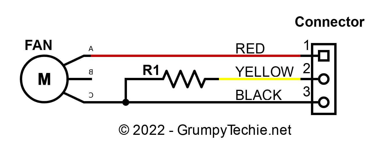
So, to achieve this is quite simple, especially since you’re forced to do some soldering anyhow to adapt the connectors to the UPS. Essentially, you cut the PWM wire from the fan, and wire a resistor between the sensor wire from the connector and ground, while wiring positive and ground to the fan. I used 82 Ω resistors that I had handy, and as long as both fans are modified this way, the fan fault went away. The resistors will only see around 0.00205 W (worst case at 5mA of sense current), so any 1/8W resistor will be plenty sturdy for the job. As the UPS is quite tolerant of value as well, I’d say a 5% tolerance resistor is good enough as well.
Categories: Tech

Which particular model of UPS do you have? Is this hack likely to work with all Eatons?
I have a 9SX
Thank you for your time and effort to publish this. It worked perfectly.
Glad it helped!
I have a 9SX 3000 rack mount, used this mod with 100 Ohm resistors I happened to have. Works great, no alarms and with some Noctua NF-A8 FLX we have an inaudible UPS. Thank you!